Bend-Tech EZ3D Software
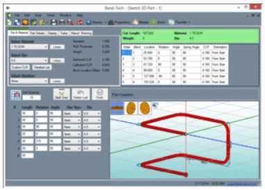
Bend-Tech EZ3D was designed for serious hobbyists. We took our easy-to-use EZ product and added a 3D interface. Our Tri-Star interface is unique in that a customer doesn’t need to learn XYZ, it uses terms like front, back, floor, ceiling, left, and right. While you are stepping quickly around the part, EZ3D is calculating your bend angles and rotations. No more guessing. A maximum of six bends per part can be done with EZ3D.
Key EZ3D Features
Designer: Sketch 3D
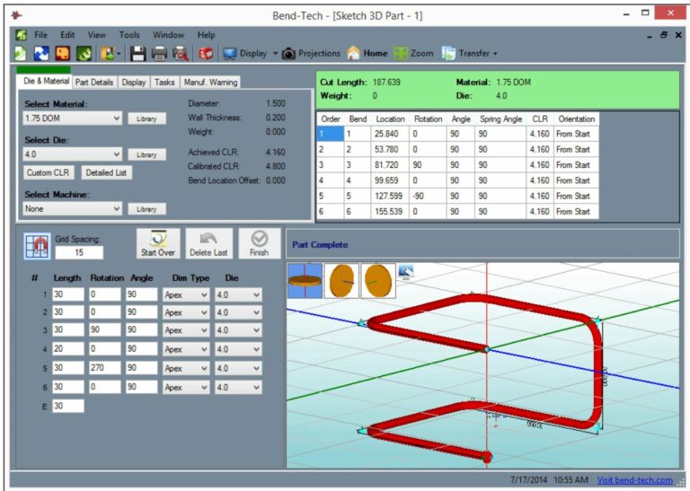
- Click-and-sketch part creation in 3D.
- Adjustable grid-snapping.
- Sketch then adjust dimensions.
- Easy switching between XYZ planes.
Designer: Harpoon
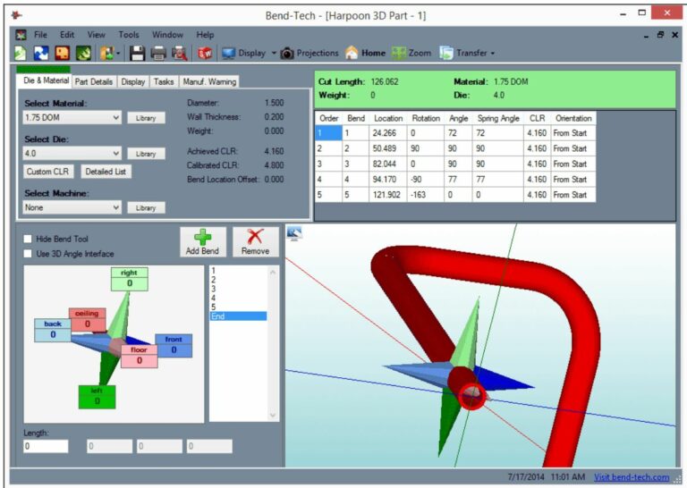
- Click-and-drag part creation.
- Add/remove bends on-the-fly.
- Intuitive drag-then-type design.
Designer: Custom Part 3D
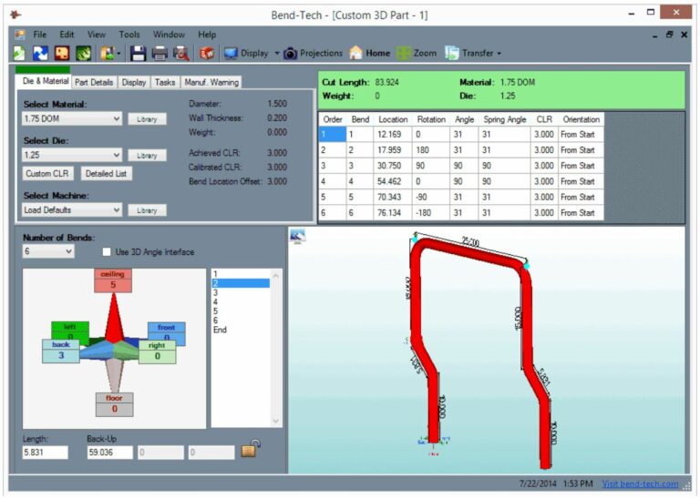
The Custom 3D Part interface allows you to enter the definitions of your part in a sequence following the center line of the material. Directional terms are easy to understand for creation of the part. These terms are; left, right, front, back, ceiling, and floor. The bend angles and rotations are automatically calculated.
Bending Simulation
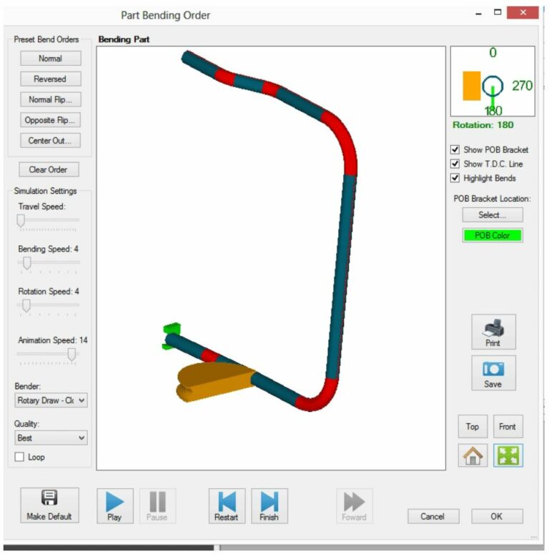
- Simulation helps the fabricator visualize the bending process before running the part through the machine. This helps to confirm the manufacturability of the part and the bend order. (*Does NOT check for collision.)
Bend Order Manipulation
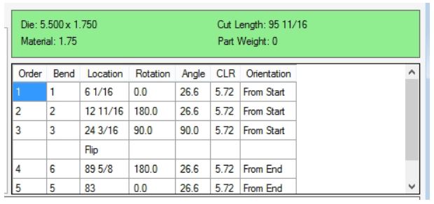
Bend from either end, flip the part between any of the bends, or do a custom sequencing. Verify your sequence using the Bending Simulation.
Designer: Custom Part
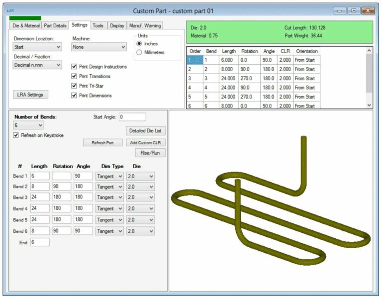
Create a part by starting at one end and entering the distance between bends, rotations between bends, and the angle for each bend. The length values can be apex or tangent values.
Designer: Sketch 2D
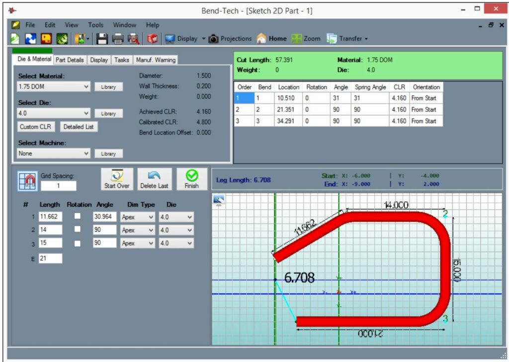
- Click-and-sketch part creation.
- Adjustable grid-snapping.
- Sketch then adjust dimensions.
- Simple, easy-to-use 2D design.
Designer: Templates
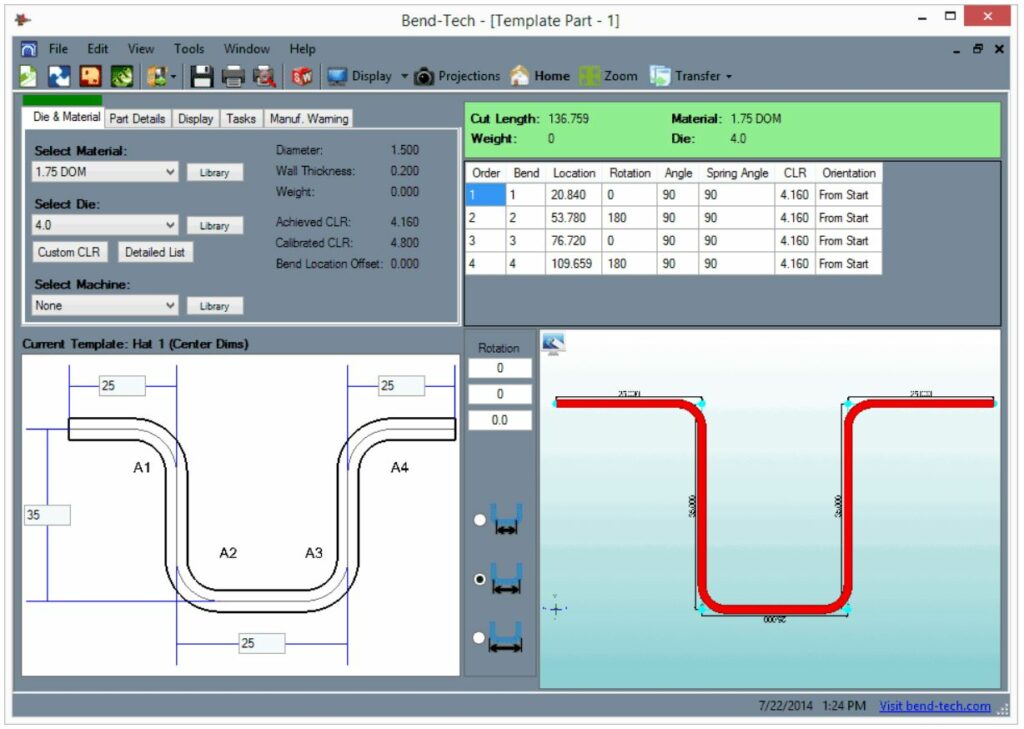
Choose from dozens of predefined templates. The templates are easy to use and in seconds you will have your design completed and be ready to start bending.
Designer: Custom Part 2D
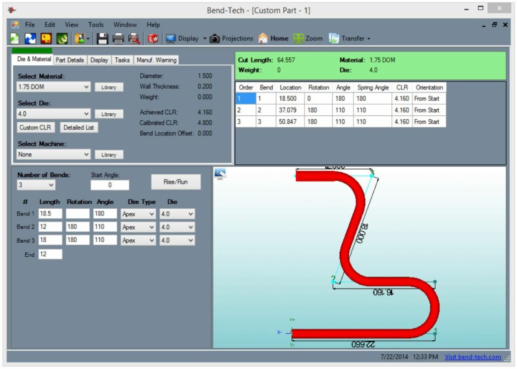
Create a part by starting at one end and then entering in the distance between bends and the angle at each bend. The length values can be apex or tangent values. Custom Part 2D allows bends to reverse direction (180 degree rotation).
Material Library
The Material Library includes material shape, size, wall thickness, color, and weight.
Die Library
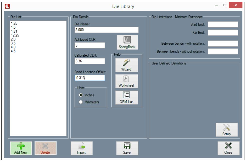
Define your dies within the software. Definition includes CLR, Calibrated CLR (stretch factor), and Bend Location Offset.
Bend Calculation Output
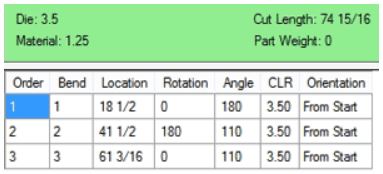
Software will provide cut length, bend locations, bend angles, and rotations for every parts you have designed. Each bend location is based from the end of the tube.
Post Bending Cutoff
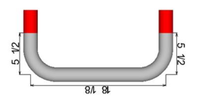
Cutoff allows extra material to be added at the end of the tube for cutting after bending. The cut length and bend locations are automatically adjusted for cutoff values.
System Requirements
Bend-Tech software requires an active internet connection in order to activate the license on your computer, and then every 6 month. SE software can run offline in between. Don’t have internet connection? See Dongle Key option.


